Written by Billy Downing
What is the driving need for dynamic application scalability?
Dynamic response to demand for a given application has become a standard expectation for performance during times of stress. A fundamental cloud ability is elasticity, in terms of resources needed to support a performant application during times of elevated usages, as well as, dormant lulls. Several reasons exist for this requirement in application design. Here are a few:
Resource utilization (Cost)
- As resources are now directly associated with cost in a cloud-native architecture, it is paramount to maintain usage based on actual need at any given time rather than overprovisioning resources which sit idle a majority of the time.
Application Performance
- Expectations for application uptime and performance can determine the overall adoption of success of an application given the sea of alternatives that likely exist. Manual intervention at times of stress is not feasible due to the speed at which traffic bursts may occur coupled with the potential complexity associated with scaling an application out without proper automation in place.
Application Resiliency
- As components of an application become overwhelmed, there is the chance of failure under load. The ability to dynamically scale an application to meet demand affords each process the predictable performance expectations set by administrators and developers based on known success metrics. (I.E, process A is performant up to 80% CPU utilization, etc.)
Kubernetes natively supports the ability to dynamically scale application horizontally, through creation of pods within an autoscale group based on predetermined metrics for load discovered through K8s metrics services, or third party.
What is Tanzu Kubernetes Grid
Tanzu Kubernetes Grid is VMware’s offering to support automated provisioning of best-practices based Kubernetes clusters with known-good components across a myriad of platforms. In short, TKG is VMware’s upstream K8s conformant deployment bundling native K8s with the necessary add-on services required. These include integration with NSX-T (for on-prem deployments) for North/South routing, Calico for east/west, ClusterAPI for lifecycle management, and various authentication and security services as well. TKG clusters can be deployed in several ways. ClusterAPI enabled K8’s cluster, using a normal Kubernetes manifest through the TKG UI/CLI using K-IN-D (Kubernetes in Docker), or directly through Tanzu Mission Control to various cloud providers.
Regardless of the deployment method, the end result is a best-practice built Kubernetes infrastructure that supports the dynamic creation of all the expected K8s objects (deployments, pods, services, etc.). This includes the deployment of additional Kubernetes clusters through ClusterAPI and the ability to then manage and scale those clusters as needed.
Kubernetes Autoscaling on a TKG Cluster
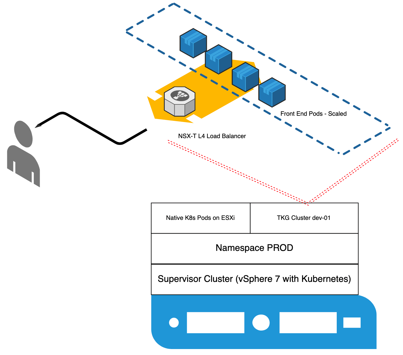
In this example, I am using vSphere 7 with Kubernetes coupled with a guest TKG cluster running a simple web application with a basic topology shown in Figure 1.
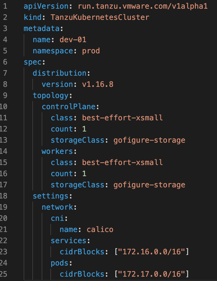
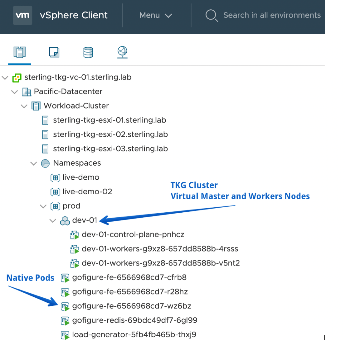
In this case, I deployed my TKG cluster using the already established Supervisor cluster as the ClusterAPI endpoint with a simple K8’s manifest (Figure 2). I then, applied it using the normal kubectl apply syntax. Therefore, the TKG cluster is treated much like any other Kubernetes object would within the cluster. In terms of VMware, it is shown in the UI as an independent object (Figure 3). All within the ‘prod’ namespace.
In this case, I have a simple web application written in Go, and a busy-box pod that will be used to generate traffic. For this demonstration, I have set the resource limits and requests very low on my deployment to allow for fast scaling of objects within my autoscale group once any sort of load occurs. Figure 4 provides the container spec for the web front end and its associated resource limits and requests.
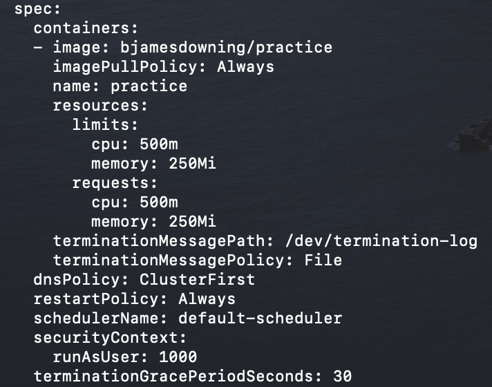
Figure 5 shows a quick review of the pods currently running on the TKG cluster, note the amount of gofigure-fe pods supporting the front end that are running.
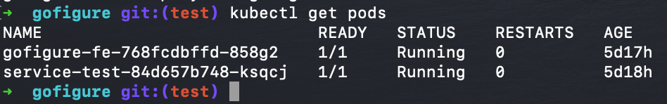
figure 5- Pods Running
At this point there is no traffic hitting the application. Therefore, as shown below in Figures 6 and 7 (using the k8s metric server), we can see the autoscale group has no load. The pods are for the most part, sitting idle. In this case I have defined a low threshold of just 10% utilization before new pods should be spun up, with a minimum of one pod and maximum of 10 pods. Before any load, as expected, the current replica amount is just one.
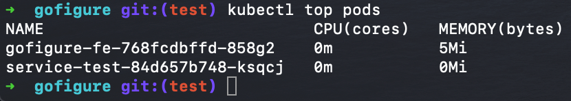
figure 6 – Metric Server Output of pod CPU Load

figure 7- Autoscale group metrics
Now we’ll generate traffic to start hitting the front end, which in this case is a Virtual IP hosted by an NSX-T load balancer (could be an AWS ALB as well) to have our application take on some stress and begin deploying more pods to handle the load. To accomplish this in a test environment, a simple while loop from the busy-box pod to continuously hit the main page of the web app will suffice.
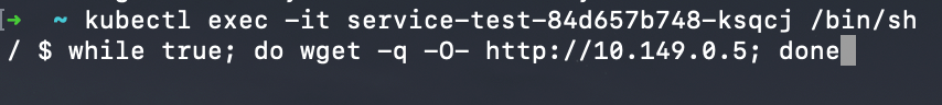
figure 8- Load Generator
Now we can see load hitting our application and based on that load we see the subsequent pods being creating and being added as endpoint behind the service to distribute the load. Figure 9 is a repeat of the previous autoscale group showing a successful scale out of the application. It has managed to deploy an additional six pods making seven in total to keep the load of each pod below the 10% CPU utilization target.
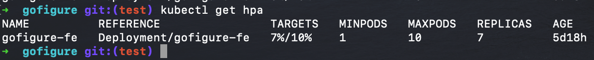
figure 9- Application successfully scaled
Furthermore, we can see the new pods running, their respective CPU load, and each of them coming up as endpoints attached to the existing load balancer service in Figures 10 and 11. All done dynamically without intervention, set off by a spike in load.
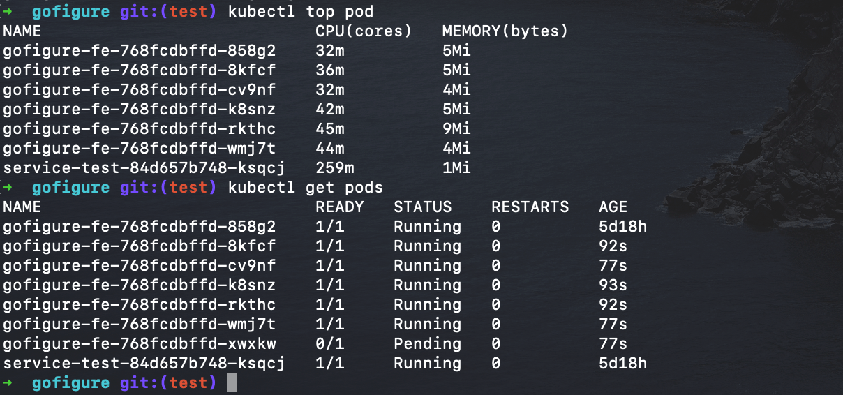
figure 10 – New pods and pod CPU usage
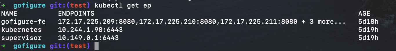
figure 11 – New pods added to service as endpoints to distrubute traffic
Once the demand ceases and the CPU of each pod begins to decrease, pods will begin being deleted until the minimum number of pods is met again to provide the necessary elasticity we’d expect from out cloud native applications.
Business driver for solution specific to TKG
Tanzu Kubernetes Grid provides the mechanism to deploy and maintain best practice-based Kubernetes clusters, which provide the platform for these add-on services to utilize horizontal pod autoscaling. Horizontal or vertical pod autoscaling does require platform tools that are not deployed to a Kubernetes cluster out of the box. For example, using Kubeadm. TKG aggregates all the tools necessary, ClusterAPI, Kubeadm, Calico, Authentication, etc. for a scalable solution without dealing with the inertia of unique k8s cluster designs.
Conclusion
Overall, what we demonstrated is the ability to deploy a best practice conformant Kubernetes cluster using Tanzu Kubernetes Grid to facilitate the platform and enable our application to autoscale based on demand. This is becoming a must-have feature for applications today as demand is increasingly associated with cost. The ability to meet any demand or spike in load, with an automated scaling response not only benefits the performance and resilience of the application, but also lessens the cost over time as the need to overprovision is no longer necessary.