Written By Billy Downing
Cloud Native Application Architecture
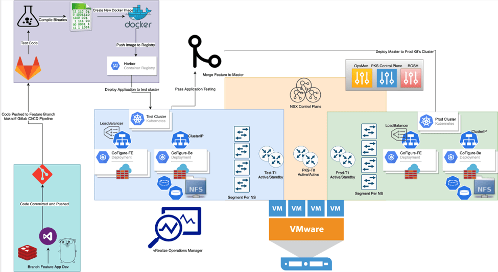
As previously discussed in Cloud Native Development On-Prem – Container Orchestration, our application is now broken into separate, independently ran services residing within containers and deployed by Kubernetes. However now that our application is broken into micro services, we need to build a fabric for them to communicate. Kubernetes provides a standardized interface to translate objects into tangible network infrastructure referred to as the Container Network Interface (CNI). In our use-case we will utilize NSX-T 2.5.1 as the network and security fabric for both our infrastructure nodes (Kubernetes masters and workers) as well as the application pods themselves.
Goal: Utilize NSX-T to create a dynamic network fabric to support our Kubernetes workloads while providing security, routing, overlay, visibility, NAT, and load balancing services.
What is NSX-T, and how does it Provide Value
VMware’s NSX-T is a software defined networking solution which defines all objects in code rather than physical equipment. Firewalling, routing, load balancing, NAT, and monitoring can all be done using NSX-T for container workloads as well as traditional virtual machine and even physical boxes.
Kubernetes allows developers and operators to package the infrastructure required to run an app within the application deployment manifest itself. For example, while an application may have a web server in front, typically a load balancer is deployed to proxy traffic and distribute as necessary. In addition, firewall rules are put in place to protect the application, and backend storage is provisioned for persistent data. In a traditional environment, each one of these components would be provisioned independently and not as a cohesive unit of deployment. With NSX-T adherence to Kubernetes CNI we can dynamically provision infrastructure during application deployment time. Explained further when visualizing the solution, NSX-T is able to abstract a physical data center and provide all the connectivity and services required to deploy a successful production-grade application dynamically and repeatedly through code.
The ability to dynamically instantiate network objects is paramount when creating test environments quickly for code deployments. As part of the CI/CD process, when code is checked in, compiled, pushed, and pulled back down it must be placed in a temporary environment to undergo application testing before being pushed to production. NSX-T allows developers to quickly consume network resources which mimic that of production allowing them to feel confident in their stage environment for application testing.
Visualize the Solution
Using a map built out within vRealize Network Insight we can visualize the objects created within NSX-T by our Kubernetes manifest. Figure 1 is a depiction of the gofigure-fe service portraying the connection to the T0 router providing north/south routing, the T1 routing for east/west, NAT, and hosting the loadbalancer, as well as the various logical switch ports associated with the overlay segments all trailing back to the three deployed pods within the gofigure-fe ReplicaSet.
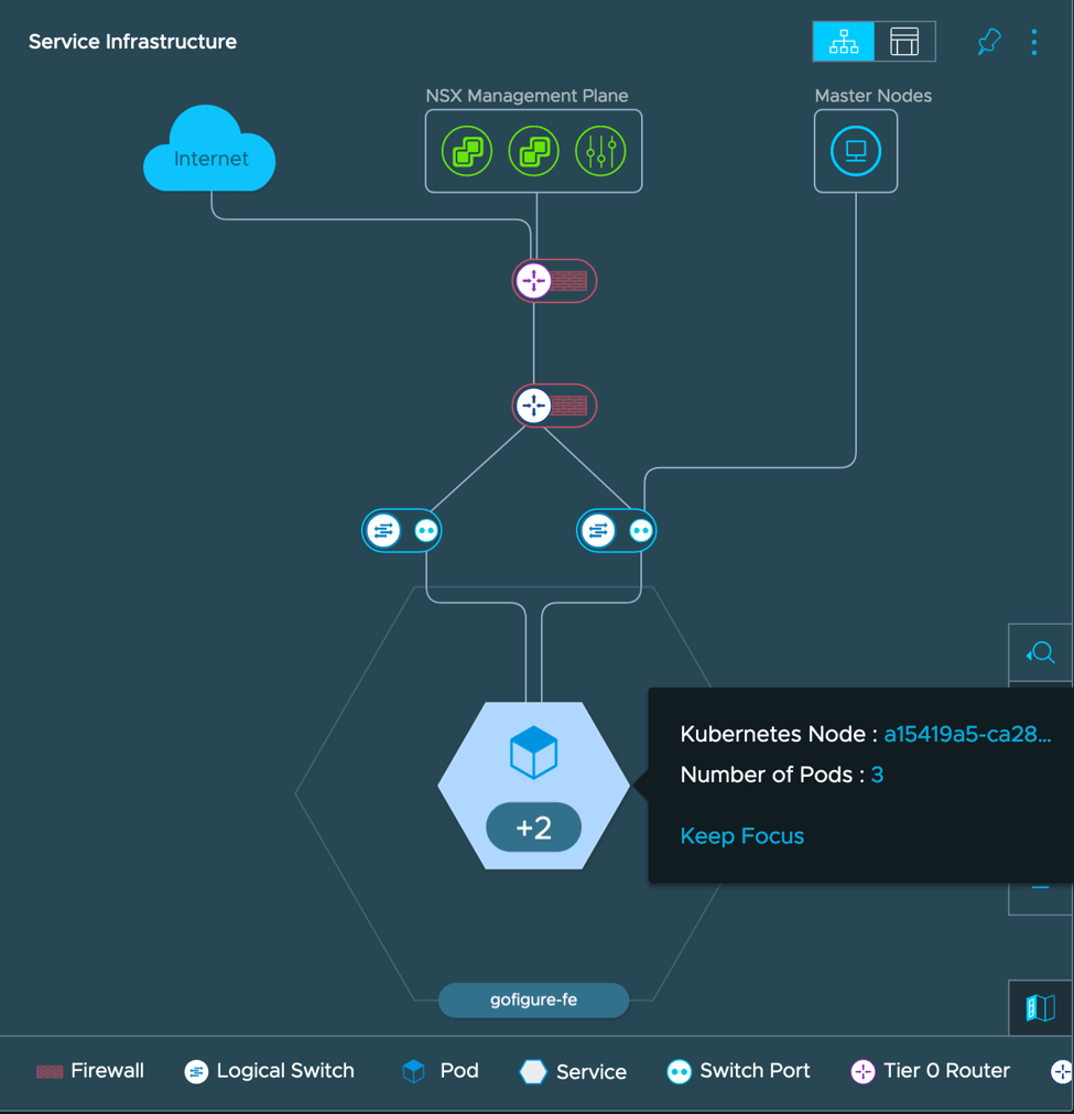 Figure 1
From the K8’s Perspective, our app is simply made up of a front-end web server and back-end key-value database tied to persistent volume over NFS. Figure 1 is an output of all the object currently created to support our application in the prod-cluster environment. In this output we can see five pods running (three web-tier and two DB tier), two services (one type Cluster and another type Loadbalancer), and the associated deployments and ReplicSets all within the default namespace of the K8’s cluster.
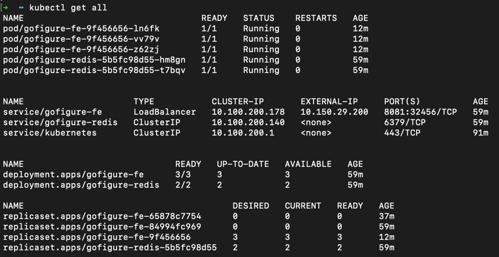 Figure 2
We can relate this infrastructure to our NSX-T environment as shown in the below series of figures the associated overlay segment, T1 router, and LoadBalancer VIP matching the IP and port allocated within the K8’s cluster, 8081 and 10.150.29.200 respectively.
Figure 3 displays the overlay segment associated with the default namespace on our cluster where we can see each pod physically connecting to the fabric (3 gofigure-fe, 2 gofigure-redis containers).
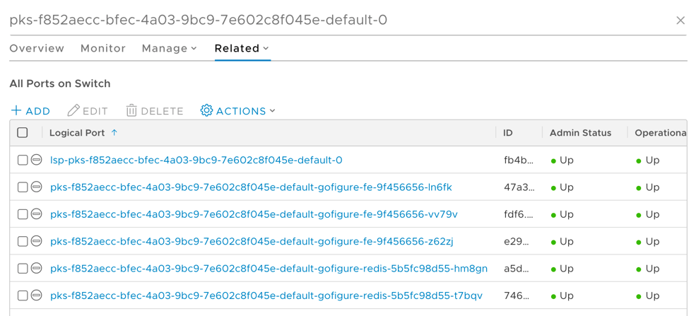 Figure 3
Moving up the stack, we can see in Figure 4 the T1 router providing services (hosting the load balancer, NAT, and route redistribution) for our application, all dynamically created by Kubernetes using the NSX-T Container Plugin (NCP) via the Container Networking Interface (CNI). Each cluster is allocated a T1 ‘cluster-router’ which hosts the loadbalancer and necessary VIPs, conducts all required NAT, east/west routing, and any other services
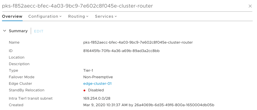 Figure 4
Within the T1 cluster router there resides a cluster loadbalancer used to instantiate services of type load balancer, ingress controllers, and provide master node resiliency. In Figures 5 and 6 take note of the gofigure-fe virtual server (layer 4), cluster virtual-server (layer 4), and Ingress controller http ruleset (layer 7).
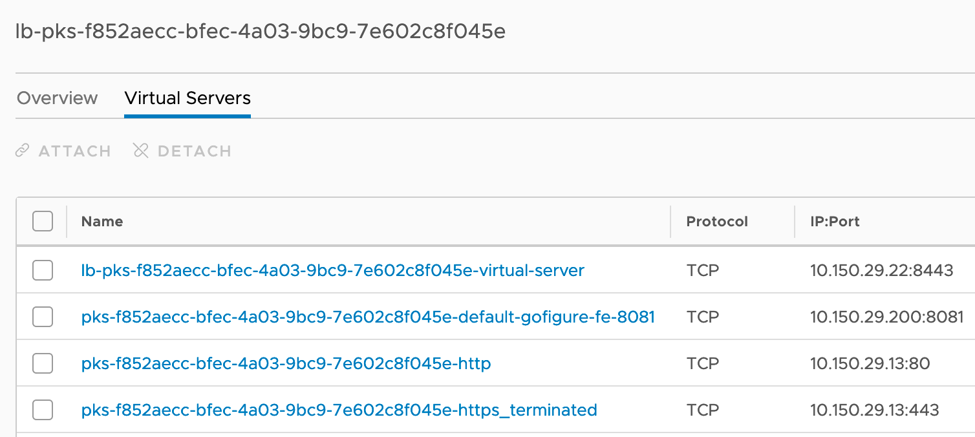 Figure 6
Figure 7 shows the load balancer forwarding rules created by Kubernetes as an ingress controller.
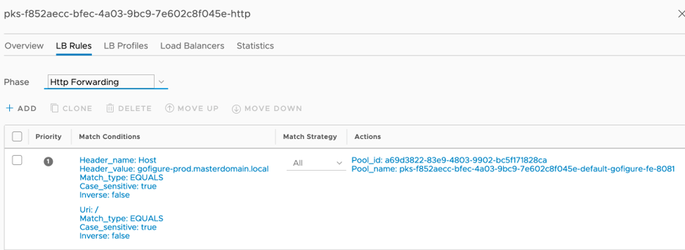 Figure 7
NSX-T also provides security at the logical interface (container) level via distributed firewall rules which can be instantiated and applied to containers based on tags during deployment. Figure 8 shows a series of firewall rules created by Enterprise PKS during deployment, and Figure 9 displays rules created previously by a higher tier security team which show the newly created containers falling into the rulesets based on pod tags.
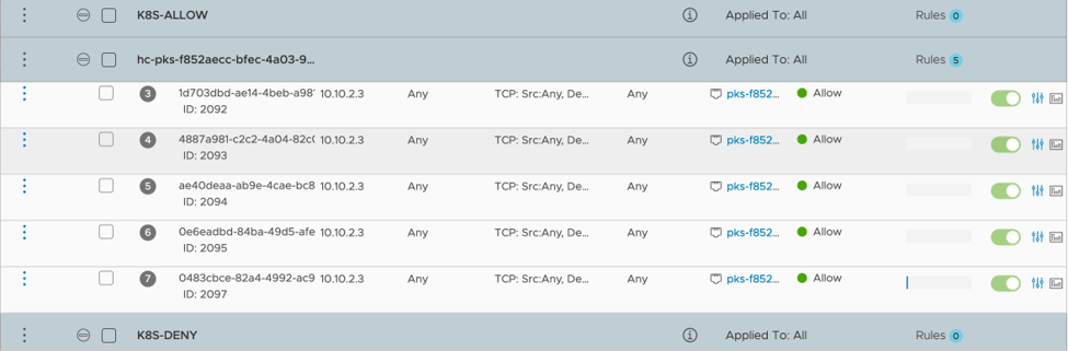 Figure 8
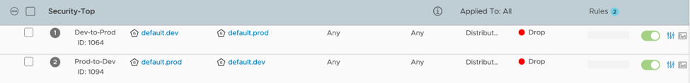 Figure 9
The intent of the firewalling method by set in the ‘Security-Top’ section is to define rules where workloads will dynamically have applied based on their tags. In this example, a security team has created rules to drop traffic from a dev environment to a prod environment and vice versa. The basis of membership is on tags, so a pods tagged with scope: env tag: prod will fall into the default.prod group while a pod tagged with scope: env tag: dev will fall into the dev group. Once deployed, these pods will be grouped into their respective environment and have traffic blocked between. Figure 10 shows the breakdown of membership for the default.prod group, which shows 5 IP’s and 5 logical ports (pods) making up the 5 production pods deployed for our application. The same is true for the dev environment which is also deployed.
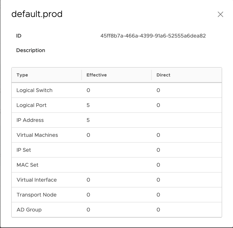 Figure 10
To confirm firewalls rules are working as expected, NSX-T offers a TraceFlow tool which generates synthetic traffic based on source and destination workloads and maps out the topology as its traversed. In Figure 11 we can see traffic between a source pod in prod, and a destination pod in dev is blocked by the pre-created firewall rules in place. If we remove that rule (shown in Figure 9) and attempt the TraceFlow again, traffic will be successful as shown in Figure 12.
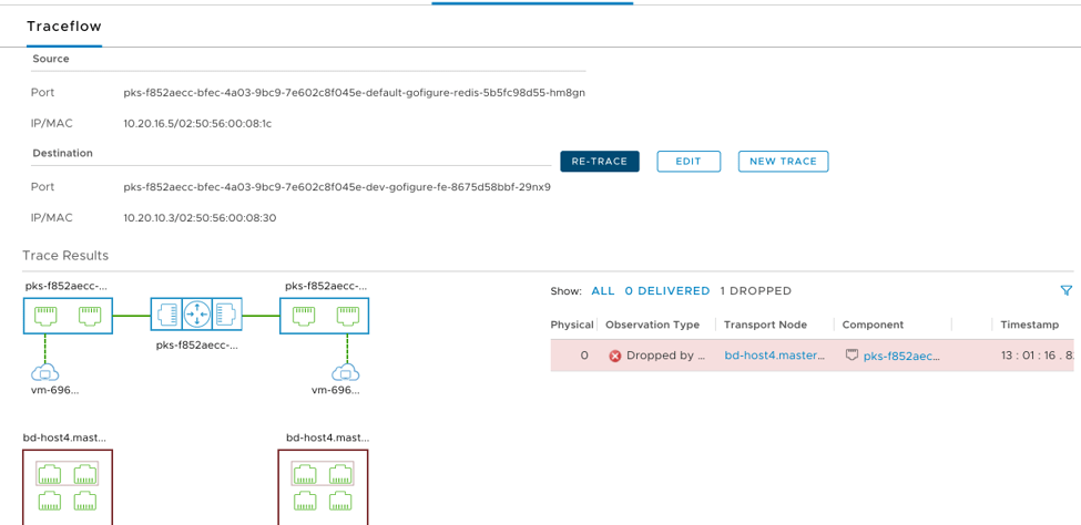 Figure 11
Figure 12 shows a successful traffic flow between the same source and destination after the rule was set to “Allow” by the security team.
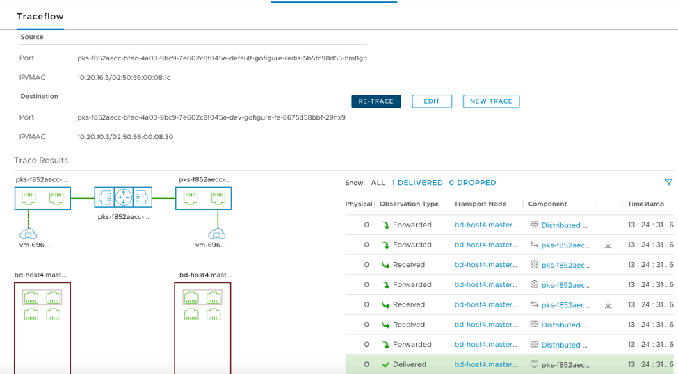 Figure 12
In the End
NSX-T provides networking capabilities with Kubernetes at the helm. Due to the software defined nature, we are able to dynamically create and destroy objects within NSX-T to support workloads in a programmatic way allowing for a repeatable pipeline process for testing and deploying out code through the below pipeline. NSX-T not only ties together the container networking, but also supports network and services requirements for the virtual machine based infrastructure.